Home
Pilz Pnoz S3 Wiring Diagram . Copies may be made for the user's internal purposes. Pnoz s3 pilz gmbh & co.
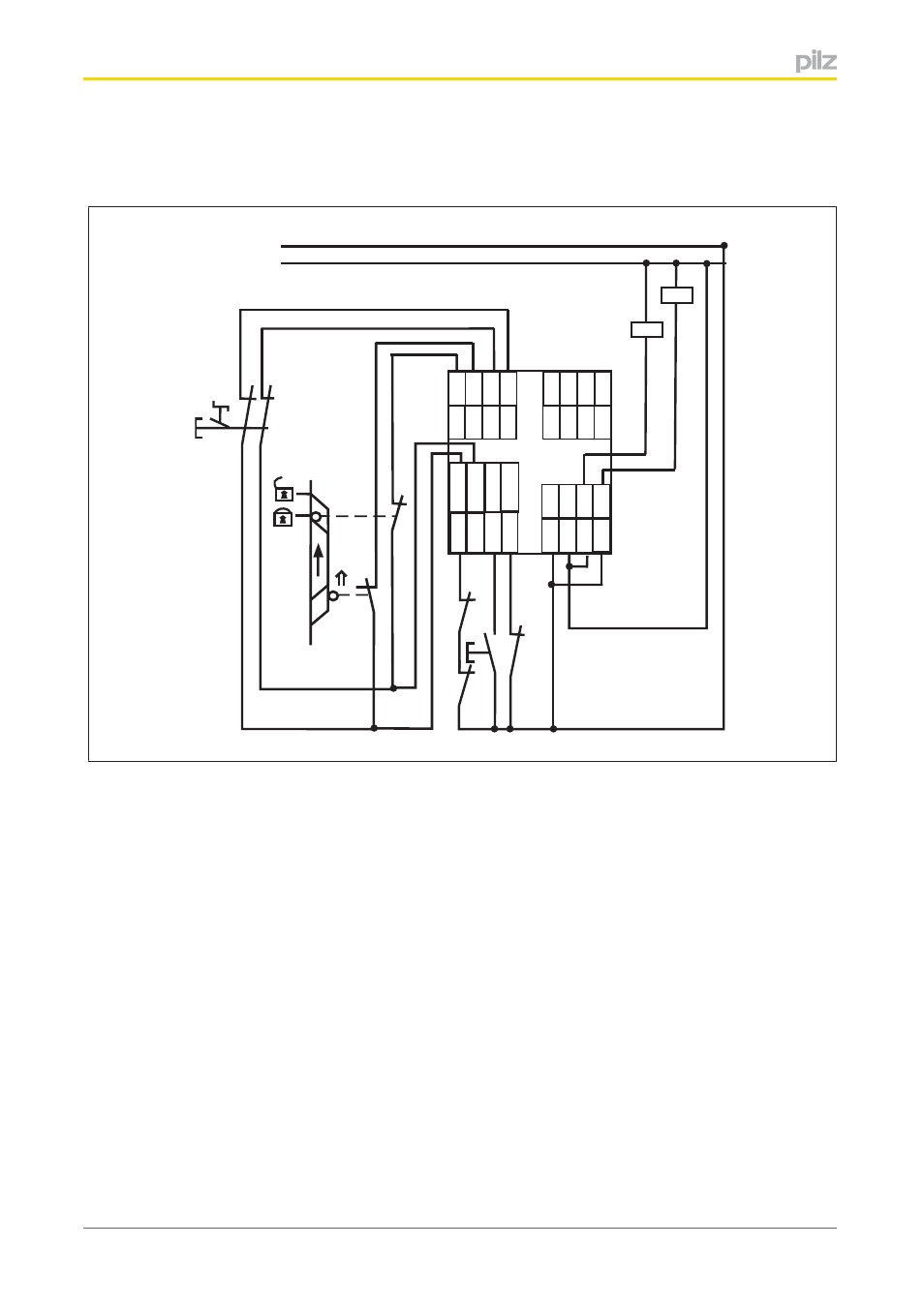
6 Connection Example Connection Example Pilz Pnoz M B0 User Manual Page 23 39 from www.manualsdir.com S3 y36 y37 schematic interior diagram a1 a2 s34y1 s11 s22 y2 41 42 s33 y36 s11 s12 13 33 14 34 k1 k2 23 24 kanal 1 kanal 2 startkreis s52 ac dc A wiring diagram usually gives guidance practically the relative direction and promise of devices and. Copies may be made for the user's internal purposes. In 1987 pilz patented the first emergency stop relay to protect man and machine. In 1987 pilz patented the first emergency stop relay to protect man and machine.
In 1987 pilz patented the first emergency stop relay to protect man and machine. Pilz pnoz s3 wiring diagram pilz pnoz x3 schematic schematics. A wiring diagram usually gives guidance practically the relative direction and promise of devices and. Pnoz s3 pilz gmbh & co. Pilz®, pit®, pmi®, pnoz®, primo®, psen®, pss®, pvis®, safetybus p®,. Quick clip showing the wiring of pilz safety relays within our controls panel. This document is the original document.
Source: m.gzcyndar.com In 1987 pilz patented the first emergency stop relay to protect man and machine. It is a track work arrangement that separates a dual gauge track into a standard gauge track and a narrow gauge track. S3 y36 y37 schematic interior diagram a1 a2 s34y1 s11 s22 y2 41 42 s33 y36 s11 s12 13 33 14 34 k1 k2 23 24 kanal 1 kanal 2 startkreis s52 ac dc
When supply voltage is supplied the power led is lit. Pilz pnoz x7 wiring diagram. When supply voltage is supplied the power led is lit.
It shows the components of the circuit as simplified shapes, and the capability and signal friends between the devices. S3 k5 k6 k5 l1 k6 s12 s34 s3 n 13 (23,33) 14 (24,34)} semiconductor output A wiring diagram usually gives guidance practically the relative direction and promise of devices and.
Source: imgv2-2-f.scribdassets.com In 1987 pilz patented the first emergency stop relay to protect man and machine. Every day, pnoz safety relays prove themselves in millions of applications worldwide. S3 s2 x1 x2 x2 t34 t12 x1 t33 t22 s1 s2 t11 t34 x2 t12 t33 x1 t22 s1 s2 t11 t11 t33 t12 x1 t22 t34 x2 s1 s3 t11 t33 t12 x1.
Pnoz s3 pilz gmbh & co. Pnoz x3 internal wiring diagram a1 a2 s13s14 s12 s21 s34 41 42 s11 s22 s31 s32 13 33 14 34 k1 k2 23 24 & y32 y31 ch2 start ch1 unit s33 ac dc b1. This document is the original document.
Pnoz xv2 pilz gmbh & co. The pilz safety relays that are shown are the pilz pnoz s3 and pilz pnoz s11 t. Pnoz s3 pilz gmbh & co.
Source: img.yumpu.com Start switch actuated element gate not closed gate closed external wiring. Safety relay wiring diagram data wiring diagram. Pnoz s3 pilz gmbh & co.
} monitored start with falling edge: Page 2 preface this document is the original document. Quick clip showing the wiring of pilz safety relays within our controls panel.
Pilz pnoz x7 wiring diagram. All rights to this documentation are reserved by pilz gmbh & co. In 1987 pilz patented the first emergency stop relay to protect man and machine.
Source: fccid.io 1nc 000922 automaten motors drives contactors relais starters. Page 2 preface this document is the original document. Safety relay wiring diagram data wiring diagram.
T11 t12 t33 t12 x1 t22 t34 x2 s1 s3 increase in safety contacts the number of output contacts can be increased by using. It shows the components of the circuit as simplified shapes, and the capacity and signal links between the devices. It shows the components of the circuit as simplified shapes, and the capability and signal friends between the devices.
All rights to this documentation are reserved by pilz gmbh & co. It is a track work arrangement that separates a dual gauge track into a standard gauge track and a narrow gauge track. All rights to this documentation are reserved by pilz gmbh & co.
Source: Safety relay wiring diagram data wiring diagram. 1nc 000922 automaten motors drives contactors relais starters. Every day, pnoz safety relays prove themselves in millions of applications worldwide.
The relevant licence information is available on the internet on the pilz homepage. It shows the components of the circuit as simplified shapes, and the capability and signal friends between the devices. When supply voltage is supplied the power led is lit.
All rights to this documentation are reserved by pilz gmbh & co. S3 y36 y37 schematic interior diagram a1 a2 s34y1 s11 s22 y2 41 42 s33 y36 s11 s12 13 33 14 34 k1 k2 23 24 kanal 1 kanal 2 startkreis s52 ac dc Quick clip showing the wiring of pilz safety relays within our controls panel.
Source: In 1987 pilz patented the first emergency stop relay to protect man and machine. Pilz®, pit®, pmi®, pnoz®, primo®, psen®, pss®, pvis®, safetybus p®,. Pnoz x3 internal wiring diagram a1 a2 s13s14 s12 s21 s34 41 42 s11 s22 s31 s32 13 33 14 34 k1 k2 23 24 & y32 y31 ch2 start ch1 unit s33 ac dc b1.
S3 k5 k6 k5 l1 k6 s12 s34 s3 n 13 (23,33) 14 (24,34)} semiconductor output It shows the components of the circuit as simplified shapes, and the capability and signal friends between the devices. Pilz®, pit®, pmi®, pnoz®, primo®, psen®, pss®, pvis®, safetybus p®,.
} monitored start with falling edge: Block diagram/terminal configuration inputinput a1 a2 s21s22 = power reset/ start s34 s11s12 = y32 (~) k1 k2 132333 142434 41 42. Pnoz xv2 pilz gmbh & co.
Thank you for reading about Pilz Pnoz S3 Wiring Diagram , I hope this article is useful. For more useful information visit https://thesparklingreviews.com/